Quest Float Suite Connection Box

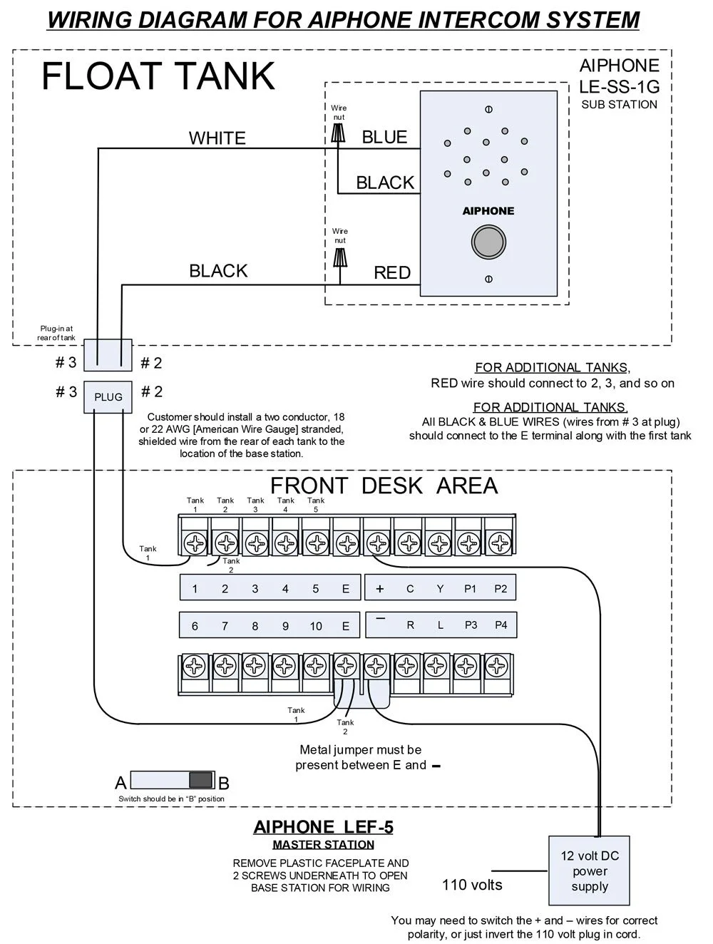
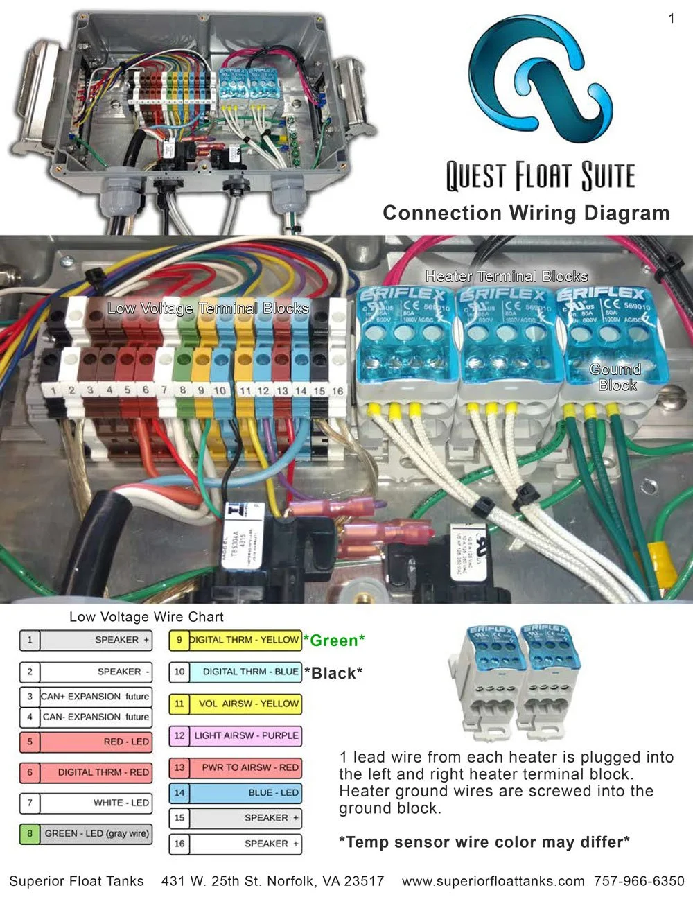
These are the pictures of the Quest Float Suite electrical connection box.  

Versions of the connection box have pre-installed connectors for the temp sensor, light, and speakers. 

Download: Quest Connection Box (PDF, 2 pages)

QFS-Connection-box-1-sml.jpg

Still need help?

Our support team can help with anything this article doesn't cover. Contact Superior Float Tanks support.

Electrical Installation Details

The following diagram outlines the general electrical requirements for installing a Superior Float Tank. 

 
The float tanks require a 208-240V 30 Amp GFCI circuit (single phase or 3 phase are compatible).  
 
The wall outlet should be an L14-30 twist lock outlet which our provided power cable will plug into.  
 
The best GFCI that we suggest for the tank is from the GFCI Store , you would want the 4 wire version with the neutral. 
Please email or call Shane Swick below with the part# PGFI-C31A3-114D
Shane Swick
Sales/Marketing
(440) 205-7600 ext:4251

If the filtration is going to be located more than 12 feet away from the tank be sure to review the "Remote Filtration" documentation.  

PDF download link at bottom of the page. 

Electrical Layout.jpg

Downloads


Still need help?

Our support team can help with anything this article doesn't cover. Contact Superior Float Tanks support.

Remote Filtration Installation

The following documentation is for remotely locating your filtration system away from the float tank.

Remote locating the filter will help with soundproofing your float tank rooms and reduce cleaning. 

PDF Link :  SFT_Remote_Filtration.pdf

SFT_Remote_Filtration-1.jpg

remote filtration doc2.jpg
Overhead Piping.jpg
remote filtration doc3.jpg

Piping_run.jpg

Additionally, you want to run a 1.5" or larger conduit between the filtration unit and the tank for the umbilical cable which connects the filtration unit to the tank.  


Still need help?

Our support team can help with anything this article doesn't cover. Contact Superior Float Tanks support.
Anti-vibration Pad Layout (EVO)

Below is the graphic for the Mason anti-vibration pad layout.  

Each pad sheet contains 91 2"x2" pads which are spaced 6" apart from each other.  

To more easily align the pads it is suggested to use blue painters tape to create the grid on the floor and then place the pads.  Once the pads are placed on the floor a wood or starboard sheeting would be placed on top of the pads to more evenly distribute the pressure on the bottom of the tank.

EVO_PAD_Layout.jpg


Still need help?

Our support team can help with anything this article doesn't cover. Contact Superior Float Tanks support.

Gas Spring Bleeder Instructions

This is the gas bleeder instructions used for the Orb and Evolution Float Pod`s gas spring arms. 

The instructions must be followed step by step to not over-bleed gas from the springs.  WARNING: Overbleeding the gas spring can require it to be sent back to the manufacturer to be repressurized 

The following is a video that overviews decreasing the pressure of the gas springs with the bleeder gauge. 

Make sure to keep the bleeder gauge in its protective box when not in use. 

PDF Link :  Gas Spring Bleeder

Gas-spring-bleeding-sml.jpgCyKSGILCG9mwYjyF8oKkiupCYYYLphYekXXTSiJ5.jpeg


Still need help?

Our support team can help with anything this article doesn't cover. Contact Superior Float Tanks support.